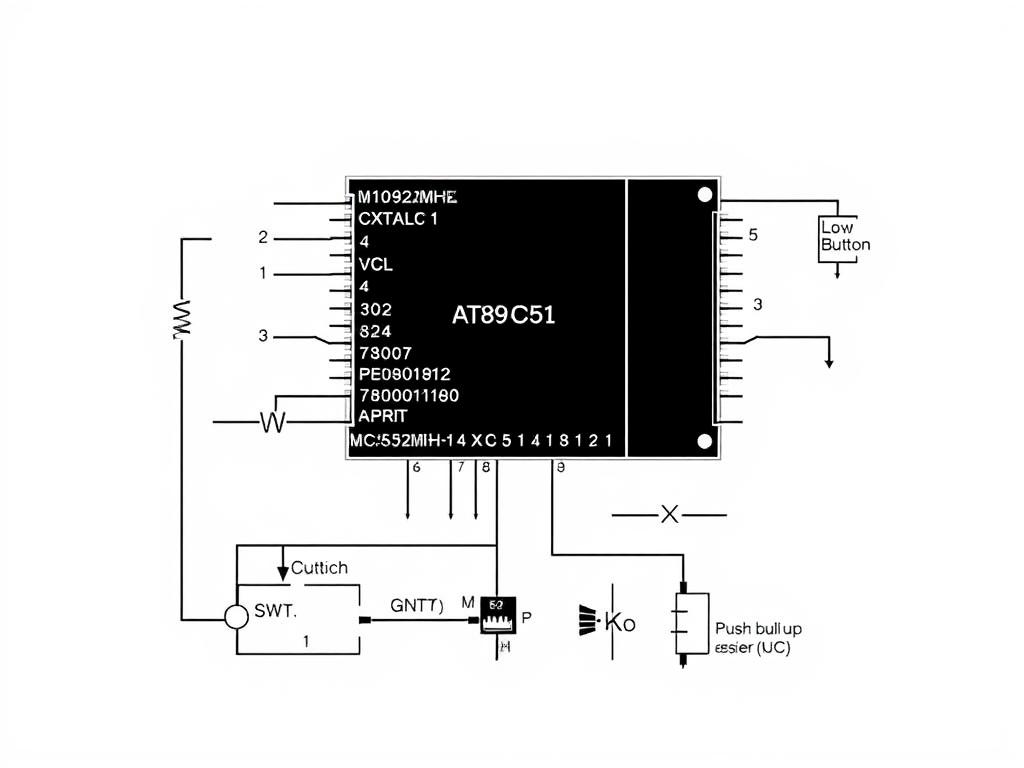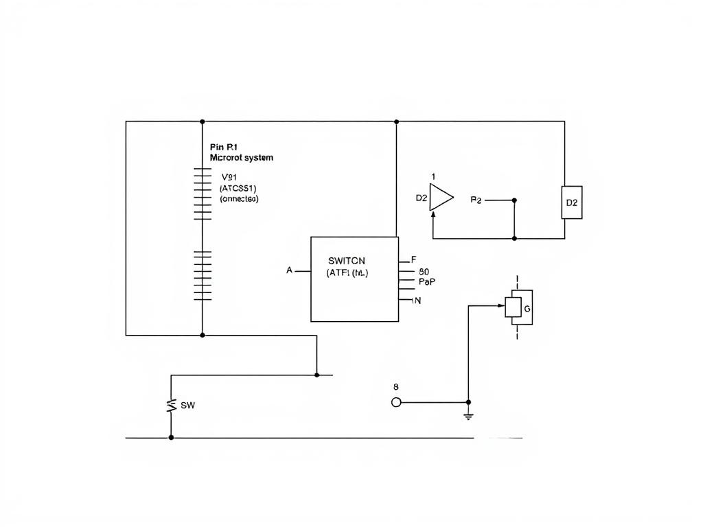
A Clear Black And White Circuit Schematic Diagram For An MCS-51 Microcontroller (AT89C51) System The
"A clear, black and white circuit schematic diagram for an MCS-51 microcontroller (AT89C51) system. The diagram must include: Microcontroller: Labeled 'U1 (AT89C51)' with standard pinout. Power: VCC and GND connections. Minimum System: An 11.0592MHz crystal oscillator connected to XTAL1 and XTAL2, with two 30pF capacitors to ground. A reset circuit with a 10uF capacitor and 10kΩ resistor connected to RST. LED Circuit: An LED (D1) connected to pin P1.0. The LED's anode is connected to VCC, and the cathode is connected to P1.0 through a 220Ω resistor (R1). (Low-level active). Switch Circuit: A push button (SW1) connected to pin P3.2 (INT0). One side of the button is connected to GND, the other side to P3.2. A 10kΩ pull-up resistor (R2) is connected between P3.2 and VCC. The style should be a clean, professional engineering schematic with clear labels for all components and pins."
20.12.2025 09:38